Front Panel Description
The device's front panel is shown in the following figure and described in the subsequent table.
Front Panel
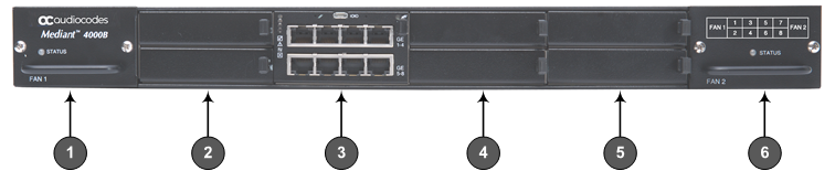
The figure provides only an example of the device's chassis. The modules housed in your device may be slightly different, depending on the ordered hardware configuration (e.g., Media Processing Module / MPM and OSN server modules).
Front-Panel Description
|
Item # |
Component Description |
||||||
|---|---|---|---|---|---|---|---|
|
1 |
Fan Tray module #1. For more information on the module, see Fan Tray Module. |
||||||
|
2 |
(Slots 1-2) Unused slots shown with two blank slot covers. The slots can house an optional, Media Processing Module (MPM). The MPM module occupies two slots. Note: The MPM is a customer-ordered item. |
||||||
|
3 |
(Slots 3-4) SBC CPU AMC module (hereafter referred to as SBC). The SBC module occupies two slots. The module provides the central processing unit (CPU), serial interface, and Ethernet port interface functionality. For more information, see SBC CPU Module. |
||||||
|
4 |
(Slots 5-6) Unused slots shown covered with two blank slot covers. The slots can house one of the following optional modules:
Note: The OSN server modules and MPM modules are customer-ordered items. |
||||||
|
5 |
(Slots 7-8) Unused slots shown covered with two blank slot covers. The slots can house one of the following optional modules:
Note: The MPM is a customer-ordered item. |
||||||
|
6 |
Fan Tray module #2 with a schematic displayed on its front panel showing the chassis' slot numbers. For more information on the module, see Fan Tray Module. |